What do the primary parameters of ESD protection components mean, and what selection criteria should be considered?
A Brief Introduction to ESD Protection Components
Static electricity is a common occurrence in everyday life. But the voltage of electrostatic charge can reach several thousand volts, which can cause significant damage to components.
ESD protection components are specially designed for small-signal electrostatic protection or surge protection and can be used for multi-channel protection. They have the advantages of compact size and multiple combined array types. They are mainly used for electrostatic protection in various communication interfaces. For example, USB, HDMI, RS485, RS232, VGA, RJ11, RJ45, BNC, SIM, SD and other interface types.
Electrostatic Discharge (ESD) devices are available in a variety of packages, including single-channel SOD-323 and multi-channel SOT-23, SOT-143, SOT23-6L, SOIC-8, and QFN-10. Circuit designers can select ESD protection diodes in different packages depending on the board layout and interface type.
How to Read the Parameters of ESD Protection Components
The following introduces the meaning of some important ESD parameters and the principles of selection.
| Part Number | VRWM(V) | VBR Min(V) | IR(uA) | IPP(A) | Cj(pF) |
| ESD5V0B15G-1006 | 5V | 5.6-8.4V | 0.08uA | 8A | 15pF |
| TPESD5Z24 | 24V | 26.7V | 1uA | 3A | 30pF |
-Reverse Working Voltage (VRWM):
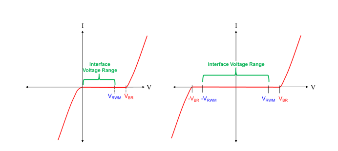
The reverse working voltage, more commonly known as the reverse standoff voltage, is the recommended operating voltage of the protected line. The working voltage is defined as the maximum positive or negative voltage that the interface signal cannot exceed to prevent unwanted leakage.
-Breakdown Voltage (VBR):
The breakdown voltage is the limit at which the ESD device begins to conduct significant amounts of current when exceeded. The figure below shows the voltage range and breakdown voltage for a unidirectional ESD diode and a bidirectional ESD diode.

– Reverse Leakage Current (IR):
Reverse leakage current refers to the ESD leakage current measured when a VRWM voltage is applied to both terminals of the ESD device.
– Peak Pulse Current (IPP):
Peak pulse current is typically measured using an 8/20 µs waveform. The selection of the ESD flow capacity, IPP, is based on the maximum inrush current that may occur on the line to select the appropriate IPP model.
– Junction Capacitance (CJ)
The junction capacitance and ESD chip area are all related to the operating voltage of an ESD protection device. For ESD products with the same voltage, the junction capacitance increases as the chip area increases. For ESD with the same chip area, the higher the operating voltage, the lower the junction capacitance.
When selecting an ESD capacitance value, it is important to consider the scenario in which the ESD is applied. If it is applied in a power supply scenario, a normal capacitance value can be used. However, if the application scenario involves a signal interface such as a USB or I/O port, it is advisable to select a low capacitance ESD protection device. The faster the signal propagates and the higher the signal quality required, the lower the tolerance value is generally selected for optimal performance.
ESD Protection Components Selection Considerations
In addition, the following issues should be considered when selecting ESD components.
- When selecting ESD for high-speed data lines interfaces, it is important to choose diodes with minimal junction capacitance. This helps to avoid any adverse effects on communication quality.
- ESD diodes come in two polarities: bidirectional and unidirectional. Select unidirectional ESD protection diodes for positive unipolar signals and bidirectional ESD protection diodes for bipolar signals.
- The selection of the appropriate type of electrostatic discharge (ESD) diode should be made with the assistance of experienced electronic engineers.
