Project Template Creation
1.1. Device Package Installation
1.1.1. Prerequisites
This Pack is applicable to Keil V5.27 and above versions.
1.1.2. Online Installation
Open Keil5 and click on the Pack Installer, as shown in Figure 1-2-1.

Figure 1-2-1
After clicking the Pack Installer button, the interface will pop up, click OK, as shown in Figure 1-2-2.
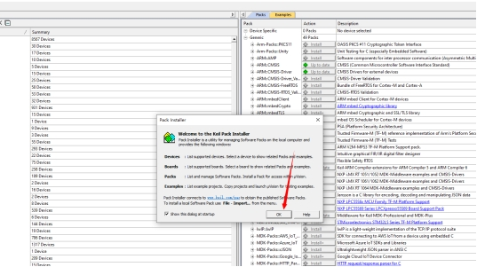
Figure 1-2-2
In the Devices tab, find the GigaDevice option, select and open it, as shown in Figure 1-2-3.

Figure 1-2-3
Select the chip model series we use, since we are using the GD32F450ZG, we choose the GD32F4xx Series, as shown in Figure 1-2-4.
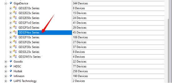
Figure 1-2-4
After selection, on the right side under the Device Specific drop-down menu, you can see GigaDevice: GD32F4xx_DFP, click the Install button on the right to download the Pack package for the GD32F4xx series products online, as shown in Figure 1-2-5.
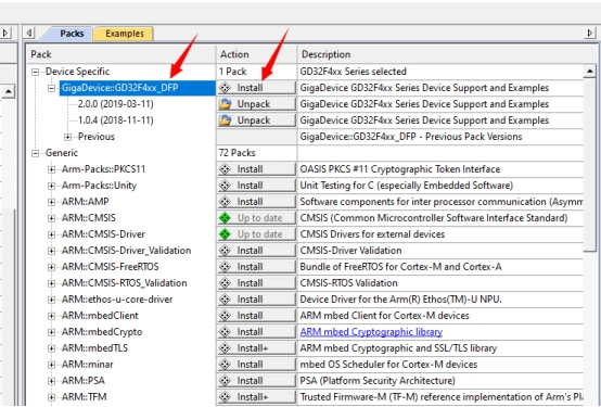
Figure 1-2-5
At the bottom of the window, you can see the download installation progress bar, as shown in Figure 1-2-6.
![]()
Figure 1-2-6
At this time, the Pack will be downloaded online to the Keil5 installation directory (…\\Keil_v5\\GigaDevice) and the installation will be completed. We can check its directory, as shown in Figure 1-2-7.

Figure 1-2-7
1.1.3. Offline Installation
Directly download the device package from the official website.
Download link: http://www.gd32mcu.com/cn/download/7?kw=GD32F4
Select the GD32F4XX AddOn, as shown in Figure 1-3-1.

Figure 1-3-1
After the download is complete, unzip it. Under the GD32F4xx_AddOn_V2.2.0\\Keil\\Keil5 directory, there is a device package, as shown in Figure 1-3-2.
![]()
Figure 1-3-2
Double-click this to install, and after the installation is complete, it will look like Figure 1-3-3.
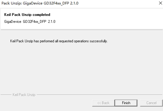
Figure 1-3-3
1.2. Standard Firmware Library Acquisition
We can download the standard firmware library from the official website.
Download link: http://www.gd32mcu.com/cn/download/7?kw=
Find the GD32F4xx Firmware Library package, as shown in Figure 2-1-1.

Figure 2-1-1
After the download is complete, unzip it. The unzipped directory is shown in Figure 2-1-2.
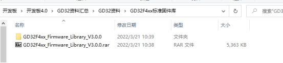
Figure 2-1-2
1.3. Introduction to the Standard Firmware Library Directory
1.3.1. Folder Introduction
Open the downloaded GD32F4xx standard firmware library, and the directory inside is shown in Figure 3-1-1.

Figure 3-1-1
- Examples: This folder contains example code written by the official, covering most of the chip’s functions.
- Firmware: This folder contains three subfolders, including CMSIS, standard peripheral library, and USB library, storing some library functions packaged by the official for user development and use.
- Template: This folder is the project template folder, containing project examples for IAR and Keil.
- Utilities: This folder contains some third-party components and development board files that come with GD32.
1.3.2. Examples
After opening the Examples folder, the contents are shown in Figure 3-2-1.

Figure 3-2-1
From the above figure, it can be seen that this folder contains routines for various peripheral resources, and each folder contains more detailed functional examples, which are of high reference value for our development of GD32 chip functions. We must read more and use more.
1.3.3. Firmware
After opening the Firmware folder, the contents are shown in Figure 3-3-1.
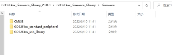
Figure 3-3-1
- CMSIS: The Cortex Microcontroller Software Interface Standard (CMSIS) is a vendor-independent hardware abstraction layer for the Cortex-M processor series.
- GD32F4xx_standard_peripheral: As the name suggests, this is the standard peripheral library for the GD32F4 series, which stores some library functions encapsulated in registers, and we will also rely on this library for development in the later programming.
- GD32F4xx_usb_library: This is the USB library function for the GD32F4 series, which can help us develop some USB applications, such as mice, keyboards, CDC serial ports, simulated USB drives, etc.
Below is a further introduction to the above folders:
The relevant introduction of each file is shown in Figure 3-3-2.
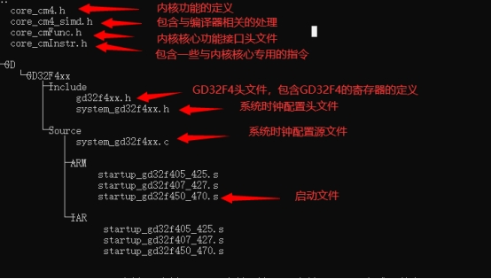
Figure 3-3-2
GD32F4xx_standard_peripheral directory structure:
This contains peripheral library files covering most of the functions of the GD32F4 chip, including ADC, CAN, SDIO, SPI, and so on.
GD32F4xx_usb_library directory structure:
There are many contents here, including audio, CDC, DFU, HID, etc. We don’t need these files for now, and we will study them later if we develop USB devices.
1.3.4. Template
The Template directory structure:
The relevant introduction of each file is shown in Figure 3-4-1.
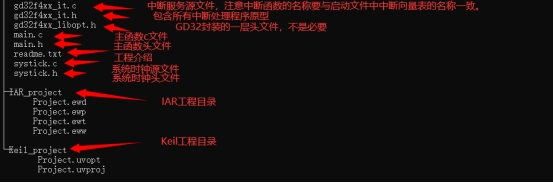
Figure 3-4-1
1.3.5. Utilities
This is a third-party component folder, which we don’t need to pay much attention to.
1.4. Creating a Firmware Library Template
1.4.1. Prerequisites
- Keil software has been installed
- GD32F4xx Pack package has been installed
- GD32F4xx standard firmware library has been downloaded
1.4.2. Creating a New Project Directory
Create a new folder named Template to save the newly created project, as shown in Figure 4-2-1.
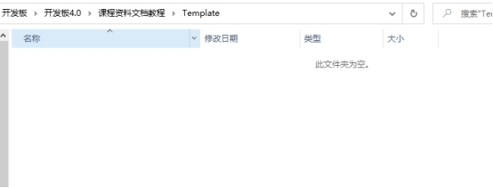
Figure 4-2-1
Then, create six subfolders under this folder, named as follows:
- Project: For project files, compilation files, etc.
- Firmware: For ARM core files, standard peripheral library files, etc.
- Hardware: For development board hardware driver files.
- App: For application layer files.
- User: For main function, gd32f4xx_it files, systick files.
- Doc: For readme.txt files, project description files.
The file directory is shown in Figure 4-2-2.

Figure 4-2-2
1.4.3. Copy Project Files
Find the download directory of our firmware library and copy all the contents under the GD32F4xx_Firmware_Library_V3.0.0\GD32F4xx_Firmware_Library\Firmware folder to the newly created Firmware directory, as shown in Figure 4-3-1.
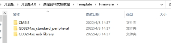
Figure 4-3-1
Create a new LED folder under Hardware for our future lighting preparation, as shown in Figure 4-3-2.
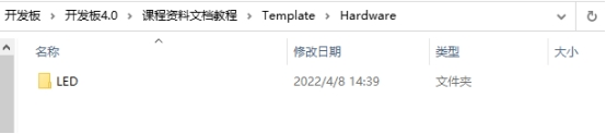
Figure 4-3-2
Copy everything except the project folder and readme.txt file from the Template folder under \GD32F4xx_Firmware_Library_V3.0.0\GD32F4xx_Firmware_Library to the newly created User folder, as shown in Figure 4-3-3.
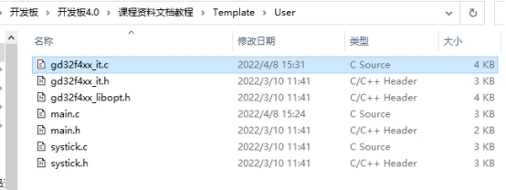
Figure 4-3-3
Create a new readme.txt file under the Doc folder, as shown in Figure 4-3-4.

Figure 4-3-4
1.4.4. Creating a New Keil Project
Open Keil, click on the Project tab at the top, and select New uVision Project to create a new project, as shown in Figure 4-4-1.

Figure 4-4-1
Select the save path as the Project folder we just created, and the file name as GD32F450, then click Save, as shown in Figure 4-4-2.
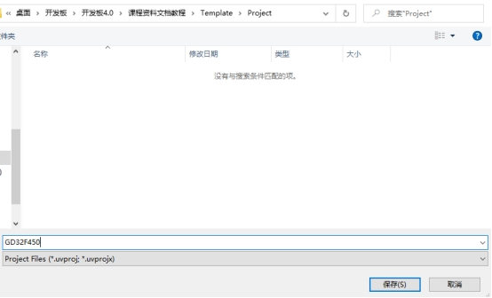
Figure 4-4-2
1.4.5. Device Selection
After saving, a project configuration window will pop up, select the required chip, here select GigaDevice -> GD32F4xx Series -> GD32F450 -> GD32F450ZG in order, and then click OK, as shown in Figure 4-5-1.
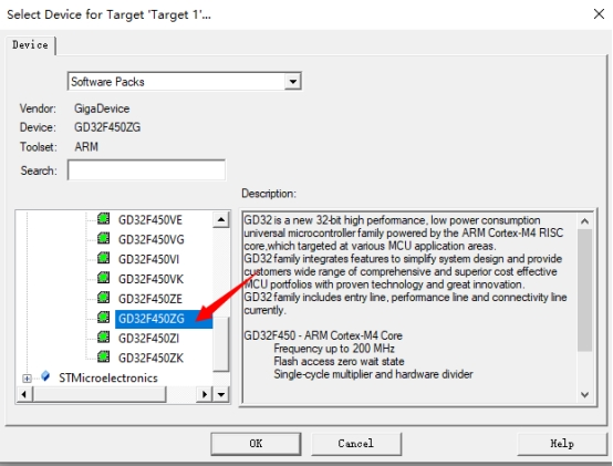
Figure 4-5-1
1.4.6. Component Selection
After confirming the required chip, a RTE environment configuration dialog box will pop up, select the components needed for the project, do not configure and click Cancel, as shown in Figure 4-6-1.

Figure 4-6-1
1.4.7. Create Groups and Add Source Files
At this point, our project has been created, but it can be seen that there are no files in the project yet, we can create some groups and add some files, as shown in Figure 4-7-1.
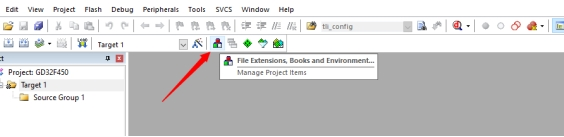
Figure 4-7-1
Create a new group by clicking the “New” button and then enter the name for the new group, as shown in Figure 4-7-2.

Figure 4-7-2
After creating the User group, click “Add Files” to add files, as shown in Figure 4-7-3.
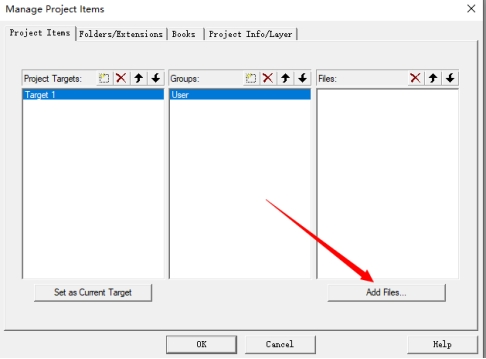
Figure 4-7-3
Then add the following files (in the User directory of the new project):
– gd32f4xx_it.c
– main.c
– systick.c
Creating groups and adding files is shown in Figure 4-7-4.

Figure 4-7-4
Create a Firmware group and then add standard peripheral library files. Add them as needed or all at once (which may slow down compilation). The rcu peripheral library must be added as it is related to the clock. Additionally, demonstrate adding a gpio peripheral library file (in the Firmware/GD32F4xx_standard_peripheral/Source/ directory of the new project), as shown in Figure 4-7-5.
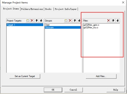
Figure 4-7-5
Create a CMSIS group and add the startup_gd32f450_470.s startup file (in the Firmware/CMSIS/GD/GD32F4xx/Source/ARM/ directory of the new project) and the system_gd32f4xx.c file (in the Firmware/CMSIS/GD/GD32F4xx/Source/ directory of the new project). Note, when adding the startup file, select “All files (*.)” as the file type because the startup file ends with .s. This is shown in Figure 4-7-6.
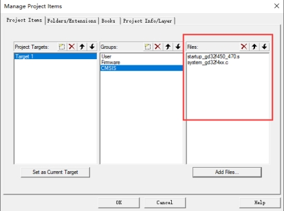
Figure 4-7-6
Create a Doc group and then add the readme.txt file (in the Doc/ directory of the new project). Make sure to select “All files” as the file type, otherwise, it will not be displayed, as shown in Figure 4-7-7.
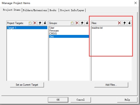
Figure 4-7-7
Create a Hardware group and temporarily do not add any files.
Create an App group and temporarily do not add any files.
All new groups are completed as shown in Figure 4-7-8.

Figure 4-7-8
After clicking OK, the project directory is shown in Figure 4-7-9.

Figure 4-7-9
1.4.8. Modify the Project Code
Open the main.c file and delete some unnecessary code. The remaining part is shown in Figure 4-8-1.
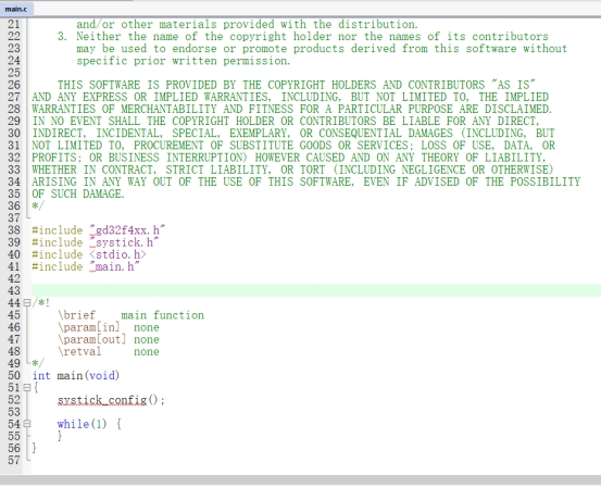
Figure 4-8-1
Open the gd32f4xx_it.c file, scroll to the end, and then delete the code below Systick_Handler. The remaining part is shown in Figure 4-8-2.
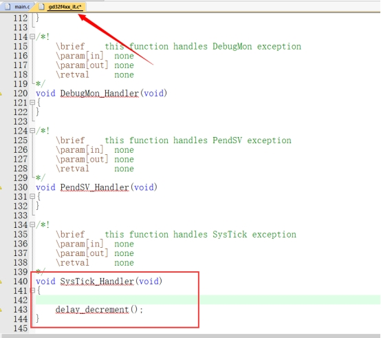
Figure 4-8-2
1.4.9. Add Macros and Header File Paths
Adding macros is to enable the header files of this chip, which is defined in GD32f4xx.h. Adding header file paths is to allow the compiler to find the corresponding header files.
To add macros:
Click “Options for target” as shown in Figure 4-9-1.
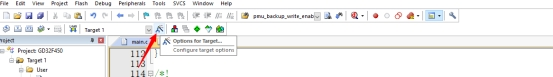
Figure 4-9-1
Select the “C/C++” tab as shown in Figure 4-9-2.
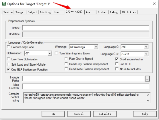
Figure 4-9-2
Enter USE_STDPERIPH_DRIVER,GD32F450 under “Define” as shown in Figure 4-9-3.
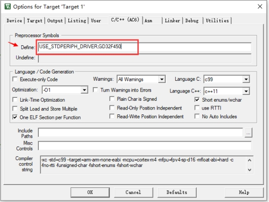
Figure 4-9-3
To add header file paths:
In the same tab, click the three dots next to “Include Paths” as shown in Figure 4-9-4.
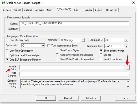
Figure 4-9-4
Click the “New” button to add a path as shown in Figure 4-9-5.
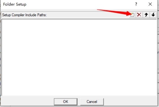
Figure 4-9-5
Click the three dots to select the path as shown in Figure 4-9-6.
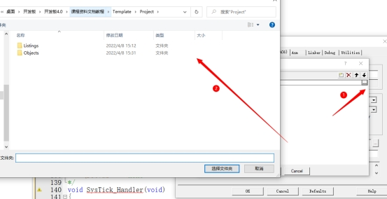
Figure 4-9-6
Select in order:
– The User directory of the new project
– The Firmware/CMSIS directory of the new project
– The Firmware\CMSIS\GD\GD32F4xx\Include directory of the new project
– The Firmware\GD32F4xx_standard_peripheral\Include directory of the new project
After adding, it is shown in Figure 4-9-7.

Figure 4-9-7
1.4.10. Configure the Project
Check “Use MicroLIB”
This is a simple library that comes with Keil and is generally used when redirecting the serial port.
Click “Options for target” and check “Use MicroLIB” under the “Target” tab as shown in Figure 4-10-1.

Figure 4-10-1
Check “Create HEX File”
The HEX file is a hexadecimal file compiled from the source code, which can be directly downloaded to the development board via a serial port or DFU.
Click “Options for target” and check “Create HEX File” under the “Output” tab as shown in Figure 4-10-2.
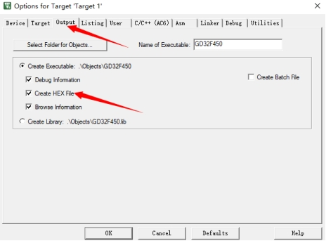
Figure 4-10-2
Change ARM Compiler version
Select version 5 for the editor, the default is 6. If version 6 is used, there may be warnings during compilation, which may be due to support issues.
Click “Options for target” and change the ARM Compiler to “User default compiler version 5” under the “Target” tab as shown in Figure 4-10-3.
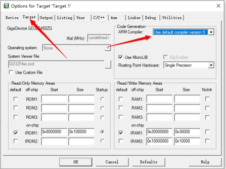
Figure 4-10-3
1.4.11. Compile
After everything is configured, you can compile.
Click the compile button to compile as shown in Figure 4-11-1.
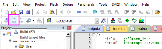
Figure 4-11-1
The compilation result is shown in Figure 4-11-2.

Figure 4-11-2
You can see 0 errors and 0 warnings. At this point, the project template creation is complete.
Related Articles:
LCSC Liangshan Development Board: Background, Hardware and Features
LCSC Liangshan Development Board Getting Started Tutorial (1)