Hello everyone, LCSC supplier Milliohm has shared with us the basics of metal alloy current sense resistors, including their parameters, structure, production process, and applications. This comprehensive overview provides valuable insights into the functionality and utility of these components in various electronic systems.
Definition and Role of Resistance
When electric charge moves through a conductor, it collides and rubs against molecules, atoms, and other particles. These collisions and friction create an obstruction to the flow of current within the conductor, which is the most evident characteristic of the conductor’s consumption of electrical energy and heat. This obstruction to the current is known as the object’s resistance. In everyday life, a resistor (Resistor) is generally referred to directly as a “resistor.” It is often abbreviated as “R” and is a fundamental property of a conductor, related to the conductor’s size, material, and temperature.
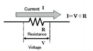
Ohm’s law states that I=U/R, and from this we can derive R=U/I. The basic unit of resistance is the ohm, represented by the Greek letter “Ω”. Ohm means the resistance to the flow of an ampere of current through a conductor when subjected to a voltage of 1 volt. The primary function of a resistor is to impede the flow of current. The term “resistance” refers to a property, while “resistor” is commonly used in electronics to refer to a component that exhibits that property. The term “ohm” is often shortened to “ohm”. Common units of resistance include kilo-ohm (kΩ), mega-ohm (MΩ), and milli-ohm (mΩ).
The primary physical characteristic of a resistor is its ability to convert electrical energy into heat. It is an energy-consuming element that, when current passes through it, generates internal energy. In a circuit, a resistor typically functions as a voltage and current divider. It allows both AC (alternating current) and DC (direct current) signals to pass through.
Characteristics and Parameters of Current Sense Resistor
Metal alloy current sense resistors are a type of resistor that utilize an alloy as the current-carrying medium. They are generally characterized by low resistance values, high precision, a low temperature coefficient, surge current resistance, and high power capacity. These metal alloy current sense resistors find applications in various electronic products, primarily for current sampling or short circuit protection. They are also known as shunt resistors due to their primary use in current detection.
The material for metal alloy current sense resistors is primarily copper alloy, with each manufacturer having unique material ratios for production and R&D. Common alloy resistor materials found on the market include manganese-copper alloy, ferrochrome-aluminum alloy, nickel-chromium alloy, kama alloy, and nickel-copper alloy, among others. These materials are chosen for their low resistance values, high stability, and high power characteristics.
Five key performance indicators of metal alloy current sense resistors: P (power), V (voltage), I (current), R (resistance value), TCR (temperature drift)
Current sampling resistance formula: I=√P/R
Power: The power of a patch resistor is the power generated due to Joule heat resistance when passing current. According to Joule’s law: P=I2 R
Rated power: the maximum permissible power at a certain temperature, usually refers to the rated power at an ambient temperature of 70℃
Rated voltage: The rated voltage can be found according to the following equation V=√P× R
Maximum Operating Voltage: Maximum voltage allowed to be loaded on both ends of the chip resistor
Rated current:I=√P/R
C.R (Temperature Coefficient of Resistance) and the resistance value of the relationship between the T.C.R. used in the unit of ppm% for the hundredths of a percent, and ppm for the millionths of a million temperature drift calculation, the resistance of each subjected to 1℃ temperature change will bring about a change in the resistance resistance value. It is calculated as:
TCR=((R2-R1)/R1(T2-T1))*10^6 (ppm/℃)
The application of positive and negative temperature drift. Positive temperature drift means that the resistance value rises when the temperature rises and falls when the temperature falls. Negative temperature drift means that the resistance falls when the temperature rises and rises when the temperature falls.
Structure of Chip Current Sense Resistor

| Item No. | Part name |
| 1 | Alloy material |
| 2 | Protective layer |
| 3 | Cu Layer |
| 4 | Ni Layer |
| 5 | Sn Layer |
Metal Alloy Current Sense Resistors Process Flow

Metal Alloy Current Sense Resistors in Circuits
The principle of the current sense resistor is to convert a portion of the current or voltage in a circuit into a measurable signal by means of a resistor dividing the voltage in the circuit according to Ohm’s law. For current sense resistors, you can use Ohm’s law to calculate the amount of current in the circuit, i.e., I=V/R, where V is the voltage difference between the two ends of the resistor, and R is the resistance value of the resistor.
For the voltage current sense resistor, the voltage divider formula serves to calculate the magnitude of the voltage of the circuit under test, i.e., U2=U1×(R2/(R1+R2)), where U1 is the voltage of the circuit under test, U2 is the voltage at both ends of the current sense resistor, R1 is the resistance of the circuit under test in series with the current sense resistor, and R2 is the resistance value of the current sense resistor.
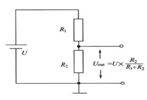
Figure 2 (high measurement sampling) will be a current sense resistor Rs series connection in the current path, the current sense resistor near the power supply VCC side, the current I flowing through the current sense resistor will produce a voltage difference, with the current sampling amplifier amplified by A times to get a voltage Vout, Vout = IRsA, the MCU ADC reads the voltage Vout, Vout can be used to calculate the back of the current size of the current flowing through the path.

Figure 3 (low measurement sampling) is also a current sense resistor Rs in series in the current path. The current sense resistor is near the power supply GND side. Because the ground connection is at one end of the resistor Rs, there is no need to measure the voltage across both ends of the resistor. It only needs to read the resistor Rs on the end of the voltage. Consequently, it only needs an ordinary amplifier to accomplish the isotropic amplifier circuit. Vout = IRsR2/R1, the microcontroller reads the voltage of Vout and then back-calculates the size of the current through the load.
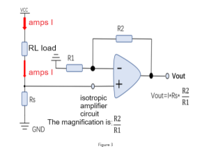
The main difference between the two methods is the difference in common mode input voltage. In high-side current sensing, the common mode input voltage is close to the supply voltage, which can be very high. For example, if the load’s power supply is 12V and the operational amplifier operates on a 3.3V power supply, you would need a specialized current sense amplifier that can handle a common mode input voltage higher than 12V.
In contrast, in low-side current sensing, the common mode input voltage is close to GND, making it lower. In this case, we can choose an ordinary operational amplifier (op-amp). However, low-side sensing also has its drawbacks, such as the potential for ground loop problems. As shown in Figure 4, the negative end of the monitored load at GND has an additional voltage drop across Rs. If other loads connected to GND do not share the same ground reference, and when the load being monitored is directly short-circuited to GND on the PCB, the current does not flow through paths 1 and 2 but instead takes the direct current path 3. At this time, the system cannot monitor the short-circuit condition of the load.
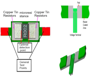
When implementing the performance of a current-sense resistor, the printed circuit board (PCB) must be designed with precision. Current sensing should be as comprehensive as possible, utilizing multiple layers and through-holes connected near the sensing component. This approach also enhances heat dissipation. The optimal method is to connect the four terminals to a two-port through-hole resistor and to use the reverse side of the PCB to route the current and voltage paths. If this is not feasible, the current and voltage detection connections should be made to the component pins on either side.
To avoid parasitic magnetic interference, the detection resistors should be mounted within the loop area, and the circuit inputs for voltage and current detection should be kept to a minimum. Additionally, the detection circuits should be positioned as close as possible to the detection resistor, and the voltage detection traces should be kept close to each other.
LCSC is a global distributor of electronic components. With over 4 million customers, we process about 14,000 orders daily. LCSC is known for quick delivery through in-stock inventory. View and select Milliohm’s current sense resistors and other products at LCSC.
